Step
3: Verify Proper Loadtypes are Assigned to Circuit Selector Addresses
Circuit Selectors do not understand MTR and FAN-FSQ loadtypes. If these loadtypes are assigned to a circuit selector the system will react slowly (if at all) to button presses (all lights may take several seconds to change state. Zones with MTR and FAN-FSQ loadtypes will not work at all). Use the Load Schedule report to determine which zones in your system use these loadtypes. Use the Panels and Enclosures Report (Panel Report) to verify that zones with MTR and FAN-FSQ loadtypes are not assigned to panels with circuit selectors.
Step 4: Verify Revision of Circuit Selector Embedded Code
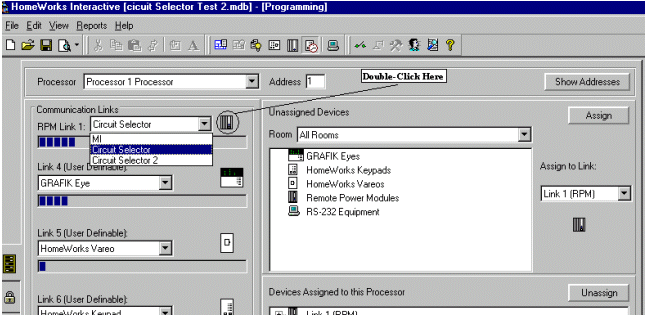
- Circuit Selector 1 - All revisions work with HomeWorks Interactive.
- Circuit Selector 2 - Must have revision level 3-50 or higher. Power the circuit selector off and back on to display the revision level. If the revision displays 3-3, or some version prior to 3-50 it will not work with HomeWorks Interactive. Obtain a replacement.
Step 5: Verify Programmed
OFF is Not Programmed
In most applications, Programmed OFF is not used. If used incorrectly, it will appear that you can’t switch your lights OFF.
In the HWI software, Electronic Bypass is mapped to Programmed OFF in the
Circuit Selector. If you accidentally program Electronic Bypass to a level other than 0%, you will be affecting the Programmed
OFF (there is no Electronic Bypass feature for Circuit Selectors). To verify that Programmed OFF levels are correct, from the Load Schedule screen,
click on Override Levels. Verify that Bypass level are all set to 0% or OFF.
To view/modify the Programmed OFF values:
- If the circuit selector is locked (View Value is blinking), you must first unlock the circuit selector – see step 10 Unlocking Circuit Selectors.
- Go into the 2nd level menu by pressing and holding buttons 2 and 5 for 9 seconds (until Select Value LED blinks).
- Use button 5 on the CS to navigate down to "Using Circuit Schedule" (this corresponds to
Programmed OFF Setting).
- The value window should display "0". If any number
appears in the value display, use button 4 to decrease the number until
"0" appears in the display.
- Use buttons 1 and 2 to view the Programmed OFF Setting for all other
circuits.
- Exit to View Value mode by holding buttons 1 and 5 until View Value LED turns on.
- Circuit Selector 2:
- If the circuit selector is locked ("Lc" is displayed), you must first unlock the circuit selector – see step 10 Unlocking Circuit Selectors.
- Go into the 2nd level menu by pressing and holding buttons 2 and 5 for 3 seconds (until Select Value LED
blinks twice per second).
- Within 3 seconds, go to 3rd level menu by pressing buttons 1, 2 and 5 for 9
seconds.
- Use button 5 on the CS to navigate down to "Circuit Level" (this corresponds to
Chicago Setting). "0" in the Value display indicates the circuit
will turn OFF when OFF is selected. Use button 4 to change the value to
"0".
- Exit to View Value mode by holding buttons 1 and 5 until View Value LED turns on.
Step
6: Verify Circuit Selectors are Addressed Properly
Circuit Selectors must be addressed to the same setting as in the software. To address circuit selectors:
- If the circuit selector is locked (View Value is blinking), you must first unlock the circuit selector – see step 10 Unlocking Circuit Selectors.
- Go into the 2nd level menu by pressing and holding buttons 2 and 5 for 9 seconds (until Select Value LED blinks).
- Use button 5 on the CS to navigate down to "Low End Trim" (this corresponds to Address Setting). Use buttons 3 and 4 to change the address to the proper setting (default address is "-").
- Exit to View Value mode by holding buttons 1 and 5 until View Value LED turns on.
- If the circuit selector is locked ("Lc" is displayed), you must first unlock the circuit selector – see step 10 Unlocking Circuit Selectors.
- Go into the 1st level menu by pressing and holding buttons 1 and 5 for 3 seconds (until Select Value LED turns ON).
- Use button 5 on the CS to navigate down until the circuit 7-segment display shows "Ad". Use buttons 3 and 4 to change the address to the proper setting (default address is "-").
- Exit to View Value mode by holding buttons 1 and 5 until View Value LED turns on.
Step 7: Verify Modules are Addressed Properly
Module addresses must correspond to the address in the software (1-6) unless using circuits 25-32. LP modules corresponding to circuits 25-32 must be connected to module link 2 on the circuit selector and must be addressed 1 and 2 (NOT 7 and 8 – as they are in the software).
Step 8: Verify Circuit Selectors are Set to Proper Baud Rate
Circuit selectors must talk to the modules at the "HI 1" baud rate. If the circuit selector is not setup for the right baud rate, the module LEDs will blink once every 7 seconds (lighthouse mode) – and will not respond to any keypad button presses. The baud rate may be checked from the circuit selector as follows:
- If the circuit selector is locked (View Value is blinking), you must first unlock the circuit selector – see step 10 Unlocking Circuit Selectors.
- Go into the 2nd level menu by pressing and holding buttons 2 and 5 for 9 seconds (until Select Value LED blinks).
- Within 3 seconds of step b, go into the 3rd level menu by pressing and holding buttons 1, 2, and 5 (until Select Value LED blinks rapidly).
- Use button 5 on the CS to navigate down to "Using Zone Capture" (this corresponds to baud rate setting in level 3). Make sure the baud rate is set for "HI". If not set properly, change it to the proper baud rate using buttons 3 and 4.
- Exit to View Value mode by holding buttons 1 and 5 until View Value LED turns on.
- If the circuit selector is locked ("Lc" is displayed), you must first unlock the circuit selector – see step 10 Unlocking Circuit Selectors.
- Go into the 2nd level menu by pressing and holding buttons 2 and 5 for 9 seconds (until Select Value LED blinks).
- Go into the 3rd level menu by pressing and holding buttons 1, 2, and 5 (until Select Value LED blinks).
- Use button 5 on the CS to navigate down until the circuit 7-segment display shows "bd". Verify the baud is set for "HI 1". If not set properly, change it to the proper baud rate using buttons 3 and 4.
- Exit to View Value mode by holding buttons 1 and 5 until View Value LED turns on.
Step 9: Verify Wiring/Link Terminators
Link 1 (MI/Circuit Selector Link) must be daisy chained with a maximum cable length of 1,000 ft (305 m). Make sure pins 3 and 4 are not swapped, or open. An LT-1 link terminator is required between pins 3 and 4 at the last Circuit Selector on link 1 when the total cable length exceeds 50’ (15 m). If an LT-1 terminator is applied incorrectly (wired between pins 1 and 2 momentarily) the internal fuse will blow and the terminator will be ineffective. To determine if the terminator has been blown, use a meter to measure the resistance of the LT-1. It should measure ~128 ohms (if blown it will measure open).
Step 10: Unlocking Circuit Selectors
- Power down the processor the Circuit Selector is connected to (this must remain off or the processor will not allow the CS to be unlocked).
- Power down the Circuit Selector.
- Hold buttons 3 and 4 on the Circuit Selector and switch the power to the CS back on.
- Keep holding buttons 3 and 4 until the View Value LED is lit solid. Now the CS is unlocked.
- Power down the processor the Circuit Selector is connected to (this must remain off or the processor will not allow the CS to be unlocked).
- Hold buttons 3 and 4 on the Circuit Selector.
- Keep holding buttons 3 and 4 until the View Value LED is lit solid. Now the CS is unlocked.
Step 11:
Verify Chicago Setting is not Programmed
Chicago Setting assigns a minimum light level for each circuit. The
circuit will never go below this level, even if OFF has been selected. To
view/modify the Programmed OFF values:
- If the circuit selector is locked (View Value is blinking), you must first unlock the circuit selector – see step 10 Unlocking Circuit Selectors.
- Go into the 2nd level menu by pressing and holding buttons 2 and 5 for 9 seconds (until Select Value LED blinks).
- Use button 5 on the CS to navigate down to "Using Zone Capture" (this corresponds to
Chicago Setting).
- The value window should display "no" if the Chicago Setting is
not used. If any number appears in the value display, use button 4
to decrease the number until "no" appears in the display.
- Use buttons 1 and 2 to view the Chicago Setting for all other circuits.
- Exit to View Value mode by holding buttons 1 and 5 until View Value LED turns on.
- Circuit Selector 2:
- If the circuit selector is locked ("Lc" is displayed), you must first unlock the circuit selector – see step 10 Unlocking Circuit Selectors.
- Go into the 2nd level menu by pressing and holding buttons 2 and 5 for 3 seconds (until Select Value LED
blinks twice per second).
- Use button 5 on the CS to navigate down to "Low-End Trim" (this corresponds to
Chicago Setting). "0" in the Value display indicates the Chicago
Setting is not used. Use button 4 to change the value to "0".
- Exit to View Value mode by holding buttons 1 and 5 until View Value LED turns on.